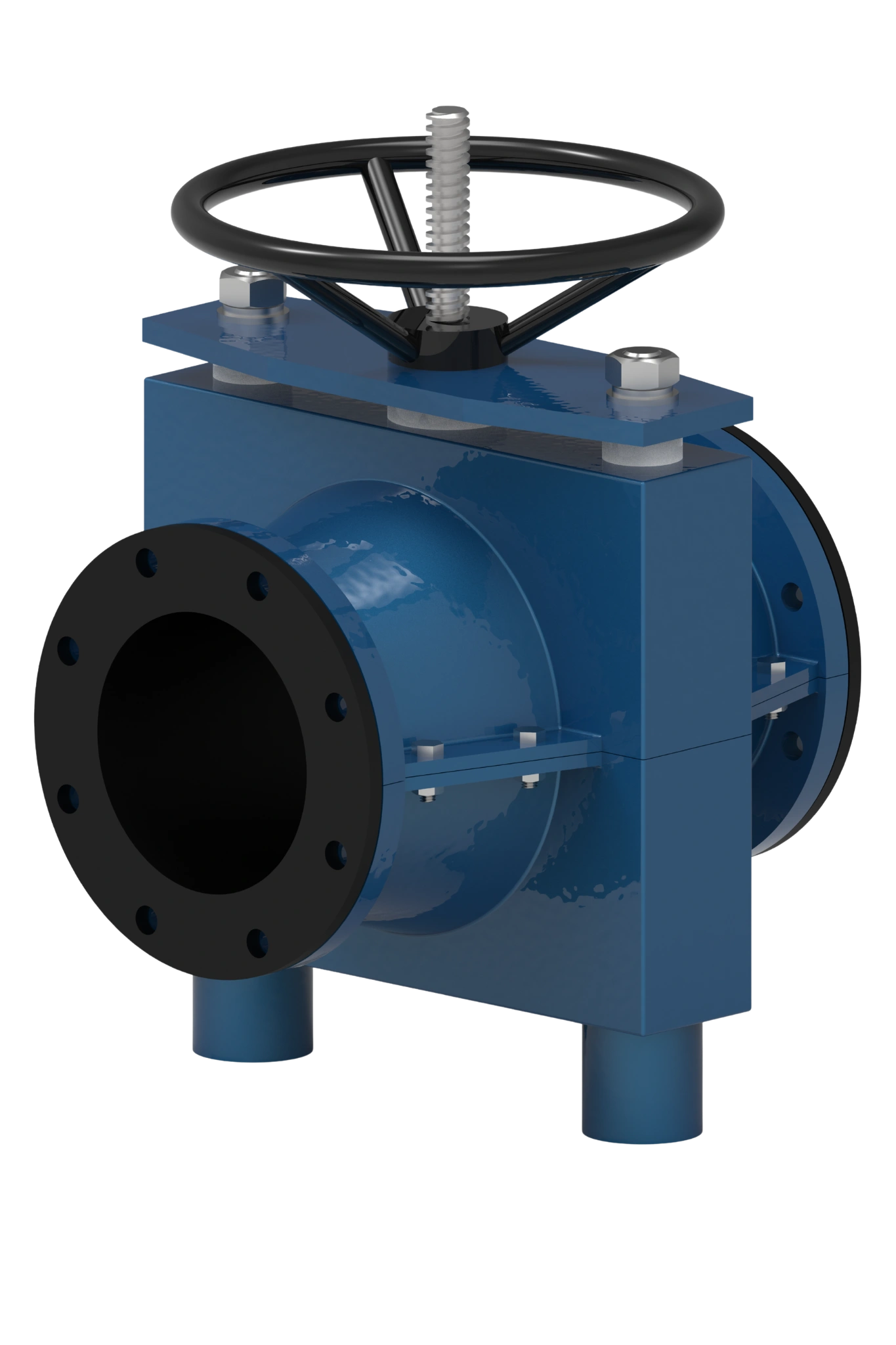
Sealed-body pinch valve 205M


Technical Specifications
 Nominal diameter DN 50-1200
- Nominal pressure PN10, PN16, PN25, PN40
- Medium temperature -60 °C ... +200 °C
- Body type Closed Hermetic
- Leakage Class «А»
- Mounting Position Any, except for downward-driven devices
- Types of Control — manual (lever) — manual (handwheel)— manual (gearbox)— pneumatic actuation — electric actuation
- Warranty Period 12 months
- Average Service Life 6 000 cycles
- Guaranteed Service Life Not less than 4000 cycles


Technical Drawings and Dimensions

Basic Dimensions Table
| DN | D, mm | D1, mm | L, mm | n-ød |
|---|---|---|---|---|
| 50 | 165 | 125 | 165 | 4-M18 |
| 65 | 185 | 145 | 165 | 8-M18 |
| 80 | 200 | 160 | 200 | 8-M18 |
| 100 | 220 | 180 | 250 | 8-M18 |
| 125 | 250 | 210 | 310 | 8-M18 |
| 150 | 285 | 240 | 375 | 8-M22 |
| 200 | 340 | 295 | 500 | 8-M22 |
| 250 | 395 | 350 | 625 | 12-M22 |
| 300 | 445 | 400 | 750 | 12-M22 |
| 350 | 505 | 460 | 875 | 16-M22 |
| 400 | 565 | 515 | 1000 | 16-M26 |
| 450 | 615 | 565 | 1125 | 20-M26 |
| 500 | 670 | 620 | 1250 | 20-M26 |
| 600 | 780 | 725 | 1500 | 20-M30 |
Tabular values for diameters DN700–DN1200 and for pressure PN16 are available upon request
Product Description
Pinch valve model 205M is designed for flow isolation and control in applications involving abrasive slurries, sludge, powders and other media containing solids. Its sealed, two-piece body houses a replaceable elastomer sleeve and a mechanism that compresses the sleeve from both sides.
The sleeve forms the flow passage and separates the process medium from the valve body during normal operation. The sealed housing provides an additional containment barrier in the event of sleeve failure, within the limits specified for the selected construction. Sleeve material, reinforcement and actuation are selected for the operating conditions.
Available configurations
- Sizes: DN 50–1200;
- Pressure ratings: PN 10, PN 16, PN 25 and PN 40;
- Body design: sealed, two-piece construction;
- Flow passage: full bore in the fully open position;
- Connections: flanged, with EN or ASME connection dimensions as specified;
- Function: on/off isolation or modulating control, depending on the selected configuration;
- Operation: manual, pneumatic or electric.
Availability of each size, pressure rating, sleeve material and actuator combination depends on the selected configuration. Flange drilling and connection dimensions are specified for the installation; an ASME flange connection does not by itself establish the valve’s pressure rating.
Design features and benefits
| Feature | Benefit |
|---|---|
| Sealed housing | Provides an additional containment barrier around the sleeve. The allowable housing pressure and containment requirements are defined for the ordered configuration. |
| Replaceable elastomer sleeve | Allows the worn flow-contact component to be replaced while retaining the valve body and operating mechanism. |
| Dual-sided sleeve compression | Opposing pinch elements compress the sleeve to reduce the flow area or close the passage. |
| Full-bore flow passage | Provides an unobstructed passage when fully open, without a gate, disc or ball in the flow path. |
| Reinforced sleeve construction | Combines a medium-contact layer with reinforcement selected for the pressure and repeated flexing duty. |
| Sleeve opening tabs | Assist the sleeve in returning to its open shape as the operating mechanism retracts. |
| Two-piece body | Can be dismantled to provide access to the sleeve and internal mechanism for maintenance. |
Typical applications
- Mining and mineral processing: ore slurries, mineral suspensions, sand handling, flotation and dewatering circuits;
- Water and wastewater treatment: sludge, grit-laden water, raw sewage and lime suspensions;
- Chemical processing: compatible chemical solutions, abrasive suspensions and process waste;
- Pulp and paper: fibre suspensions, process sludge and other solids-containing streams;
- Powder and bulk material handling: flow isolation of compatible powders and granular media.
Sleeve material selection
The elastomer sleeve is selected primarily for abrasion resistance, chemical compatibility and operating temperature. The compound and reinforcement must also suit the working pressure and operating cycle.
| Sleeve material | Reference temperature range | Typical applications and media |
|---|---|---|
| NR Natural rubber | −40°C to +80°C | Abrasive water-based slurries, mineral suspensions, sand-laden water and coal slurry. |
| NR + Linatex | −40°C to +85°C | Severe abrasive duties with the specified natural rubber lining, including sand, coal and mineral slurry handling. |
| NBR Nitrile rubber | −40°C to +120°C | Oily water, mineral oils and compatible petroleum products, including selected fuels. |
| EPDM | −50°C to +130°C | Water-based media, salt solutions and compatible dilute acids and alkalis. |
| SBR Styrene-butadiene rubber | −40°C to +100°C | Abrasive water-based media, contaminated water and selected mineral suspensions. |
| CSM Chlorosulfonated polyethylene | −40°C to +130°C | Selected chemical solutions and contaminated process media requiring a compatible chemical-resistant compound. |
| IIR Butyl rubber | −50°C to +130°C | Selected chemical duties, compatible polar solvents and applications requiring low gas permeability. |
| FKM Fluoroelastomer | −20°C to +150°C | Compatible hydrocarbons and chemical media requiring elevated-temperature resistance. |
Temperature ranges are selection references for the listed compounds, not simultaneous pressure-temperature ratings. Final suitability depends on the supplied sleeve formulation, reinforcement, medium composition and concentration, pressure and duty cycle.
Body material options
| Material group | EN designation | ASTM / other designation |
|---|---|---|
| Ductile iron | EN-GJS-400-15 | GGG40 |
| Cast carbon steel | GP240GH (1.0619) | ASTM A216 WCB |
| Cast stainless steel | 1.4308 | ASTM A351 CF8 |
| Cast stainless steel | 1.4408 | ASTM A351 CF8M |
| Aluminium alloy | According to specification | Grade selected for the configuration |
Body material is selected for mechanical requirements, housing containment requirements and the installation environment. During normal operation, chemical compatibility with the process medium is primarily determined by the sleeve. EN references do not establish automatic interchangeability with ASTM grades.
Actuation and flow control
- Manual operation: handwheel or gearbox, depending on valve size and operating force;
- Pneumatic operation: actuator selected for the required closing force and operating conditions;
- Electric operation: actuator selected for on/off or modulating duty.
For modulating applications, sleeve geometry and actuator control are selected using the required flow range and pressure drop. Position feedback and control accessories are specified to match the automation requirements.
Maintenance and replacement sleeves
The two-piece body provides access to the sleeve for inspection and replacement after the valve has been isolated, depressurised and drained. A worn sleeve can be replaced without replacing the complete valve. Maintenance intervals depend on abrasion, chemical exposure, pressure, temperature and operating frequency.
For a replacement sleeve, provide the valve model and serial number, size, pressure rating, existing sleeve material and operating conditions. A sleeve drawing or photographs help identify the correct dimensions and mounting features.
Information for valve selection
Please specify the valve size, flange standard and drilling, process medium, solids content and particle size, operating pressure and temperature, and required actuation. Include any requirements for housing containment in the event of sleeve failure. For flow control, also provide minimum, normal and maximum flow rates together with upstream and downstream pressures.


Ask them to us!
form below and send
your application to the following e-mail address